Owner : Ministry of Water & Irrigation/ Water Authority of Jordan.
Location : Ain Ghazal
Commissioning date : Macrh 2006
Project value : 179,000 JD
Contractor : Joint Venture of M/S The Morganti Group Inc. and M/S Infilco Degremont Inc.
A- INTRODUCTION
Raw Water in Ain Ghazal Station will be modified to add Screening and Aeration functios.
The screening and Aeration shall be controlled by providing two fault tolerant (Hot Redundant) PLC systems; one for screening (00PLC001) and another for Aeration (00PLC002).
The newly added PLC units will be connected to the existing Fiber Optic Wide Area Network and will run in conjunction with the existing PLC system.
The Screening and Aeration PLCs (00PLC001 and 00PLC002 respectively) shall be designed in a way to be compatible with the existing system. This shall include the proper selection of the hardware and interface modules, the proper selection of network addresses and the proper selection of the SCADA system interface modules.
The existing SCADA system shall also be modified in order to accept the Screening and Aeration PLCs.
The design of the Screening and Aeration PLCs will be done, to the possible extent, using components similar to the components used in the existing PLC system. This shall improve the maintenance works implementation and spare parts storage.
System Components
Screening PLC
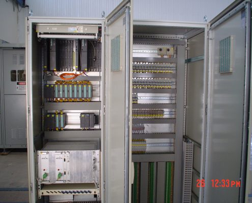
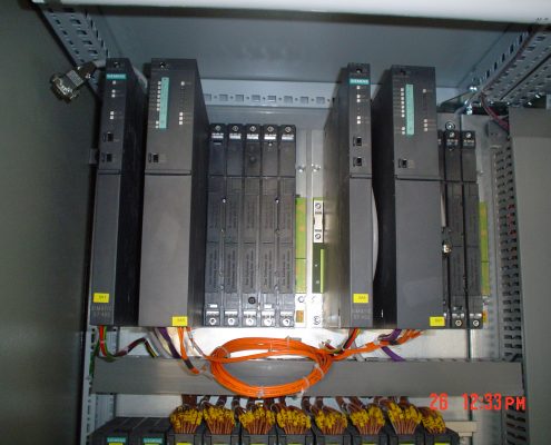
The Screening PLC (00PLC001) will be designed based on Siemens Fault tolerant, Hot redundant System. In which the PLC hardware is duplicated to achieve the highest system availability.
The hardware components will be as follows:
- PLC controller: the PLC controller will have the following components.
- Two PLC racks, one for primary controller and one for hot standby controller.
- Two rack power supplies, one for the primary rack and one for the secondary rack.The rack power supplies will provide the power for the PLC cards.
- Two processors (Siemens S7-400-414-H system), one for primary rack and one for the standby rack. The processors will do all the arithmetic and logic function of the plant.
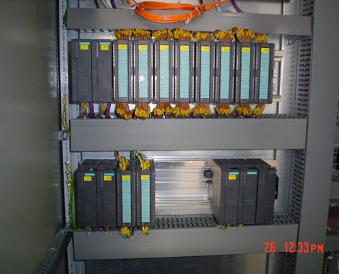
- Shared I/O: the main and standby PLC arrangements shall be linked to a shared I/Osystem in order to have all field I/O devices common to both of them. The shared I/O system is based on Siemens S7 ET200M hardware modules which will basically have the following components:
- One Rail to collect the entire shared I/Os components together.
- Redundant Profibus Interface Module (Type IM153-2) which will be part of the shared I/O rack and will link the shared I/Os to the Hot- Standby PLC system. The module will have a redundant link configuration one link for the primary PLC and another to the standby PLC.
- A set of inputs and outputs, analog and digital, cards to accommodate the required number of field I/O system.
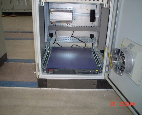
- The Screening PLC cabinet will be equipped also with a set of protection, switching and functional elements to provide the suitable working capabilities for the PLC unit.Elements like interfacing relay, power supplies, panel light …etc. will be provided.
Aeration PLC
The Aeration PLC (00PLC002) will be designed based on Siemens Fault tolerant, Hot- Redundant System. In which the PLC hardware is duplicated to achieve the highest system availability.
The hardware components will be as follows:
- PLC controller: the PLC controller will have the following components.
- Two PLC racks, one for primary controller and one for hot standby controller.
- Two rack power supplies, one for the primary rack and one for the secondary rack.The rack power supplies will provide the power for the PLC cards.
- Two processors (Siemens S7-400-414-H system), one for primary rack and one for the standby rack. The processor will do all the arithmetic and logic function of the plant.
- Shared I/O: the main and standby PLC arrangements shall be linked to a shared I/O system in order to have all field I/O devices common to both of them. The shared I/O system is based on Siemens S7 ET200M hardware modules which will basically have the following components:
- One Rail to collect the entire shared I/Os components together.
- Redundant Profibus Interface Module (Type IM153-2) which will be part of the shared I/O rack and will link the shared I/Os to the Hot- Standby PLC system. The module will have a redundant link configuration one link for the primary PLC and another to the standby PLC.
- A set of inputs and outputs, analog and digital, cards to accommodate the required number of field I/O system. The Aeration PLC cabinet will be equipped also with a set of protection, switching and functional elements to provide the suitable working capabilities for the PLC unit. Elements like interfacing relay, power supplies, panel light …etc. will be provided.
Network Components
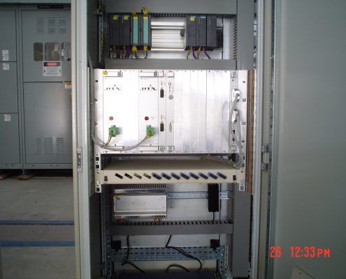
Each of the Screening and Aeration PLC cabinets will be equipped with a redundant ring Fiber optic interface module. The fiber optic interface module (called OLM) will link the electrical Profibus network connecting the processor of the PLC to the fiber optic wide area network.
Two fiber optic interface modules (OLM) will be provided for each PLC cabinet, one OLM for the primary PLC and one for the Standby PLC. The cabinet’s OLM set will be linked together from one side by a fiber optic patch cable and to the wide area fiber optic cable from the other side.
Network Specification
The fiber Optic Network Modules selected are suitable for the connection of fiber optic ring network single-mode fiber cable. The network protocol to be use is Profibus with a speed of 187.5 Kbps.
Connection to MCC Each of the PLC cabinets will be equipped with a Profibus Y-Link module. The main objective of this module is to link the redundant Profibus network to a single Profibus network. The single Profibus network will be connected to the MCC line monitoring device to collect all the needed information about the line voltages, power and current values of the MCC. The MCCs’ line monitoring device shall be selected to be equipped with a Profibus-DP port.

